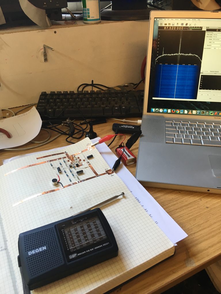
Sometimes you just want to put together a circuit for the heck of it and keep it somewhere safe. But where do you put it when it’s assembled that’s easy to poke and make notes against the circuit diagram?
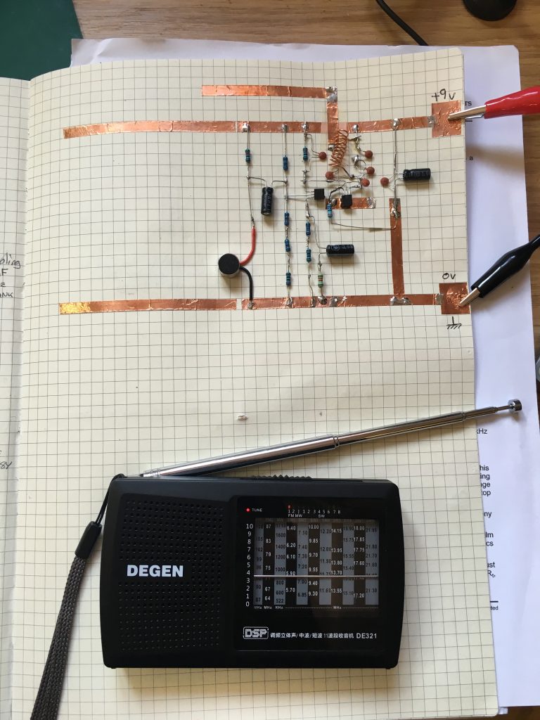
I started using dead bugged circuits in a log book which can be filed away on a book shelf for safe keeping until it’s next outing. Some call it paper circuits. The circuit diagram is in one section and the circuit itself is below it or on the next page. Sticky backed copper tape is used for power lines and to anchor the circuit to the page. The legs of through hole components usually provide the wiring or more copper tape can be used.
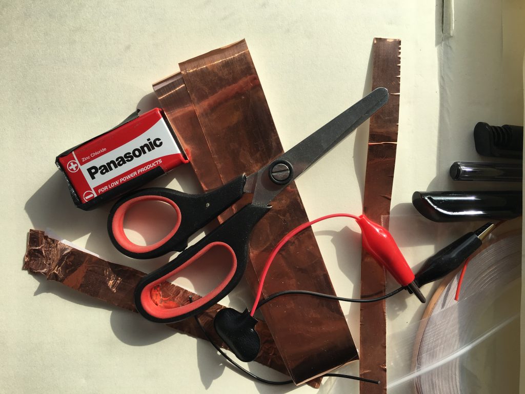
Most of the circuits I’m making can be powered from a 9 volt battery with some crocodile clips attached to copper tape at the edge of the page. Luckily I found a log book which had a pouch in the rear for all the necessaries. You just need to make sure you protect the power terminals of the battery with some thick insulation tape to stop it shorting out during storage.
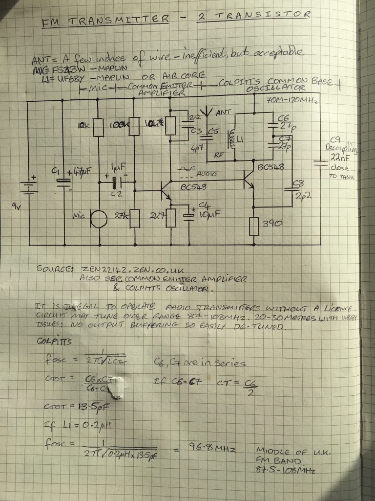
This particular circuit I’m showing you here is a good old FM radio transmitter bug. The circuit is dead bugged onto the page with a few minor part differences from the circuit diagram downloaded from t’internet. Note that i had to modify the circuit below to get it to work, see the comment about C4.
The first thing I noticed on firing it up was it didn’t work. Not a bit of bugging was going on. My bug was buggy. I couldn’t hear a thing on the FM radio sitting right next to it. It was supposed to be a quick proof of concept for the idea of log booking circuits so I let it sit for a while before coming back to it with fresh eyes which proved insightful as ever.
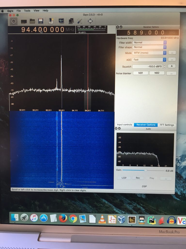
Scope probing of the output of the common emitter amplifier stage showed it was over amplifying. Inputting a 20mV sine wave from a signal generator where the microphone input was, gave a large distorted sine wave. When using an RTL SDR receiver dongle and GQRX software on a laptop you could see that the RF signal was vastly over-modulated. It was flat as a pancake and incredibly wide.
Looking at the circuit again you can see that the capacitor C4 on the emitter of the common emitter audio amplifier has no resistor in series. Just one in parallel. The DC current through the transistor was largely defined by the base voltage and emitter resistor. The AC current was largely defined by the AC base current, transistor hfe and emitter capacitor impedance. The capacitor impedance was near zero at these frequencies so the hfe defined the amplification.
Adding a resistor in line with the capacitor would fix that issue. The value needed to be chosen dependent upon the output from the microphone. But exactly what output levels would we get out of the electret microphone? Well it depends on its specification and how loud the audio source is. Rather than try to calculate it which was going to show that “it depends”, I produced a 1 kHz tone via Audacity on a laptop through its speakers, at a suitable volume to simulate voices more than 1 metre away from the bug. You use a single tone so that you can clearly see what amplification the signal is undergoing from input to output ensuring there’s no clipping or distortion of the waveform.
The first randomly chosen resistor value (1.3 kOhm) looked good. Success. But why was it needed? The transistor I used had a higher hfe than the one described in the reference circuit so it amplified the signal too much. You could also argue that the circuit wasn’t right in the first place or i made the circuit incorrectly:)
At this point again I expected success but nothing worked. After looking at the FM signal produced on the RTL SDR the modulation looked good but the frequency was shifting every time the page moved. Obvious really. Minor bending of the page caused movement of the tuned colpitts oscillator changing its frequency. So lesson learned. Paper circuits work well, but when designing RF circuits you need rigidity!