I wanted a simple bedside lamp with a continuously variable brightness. Something I could read from whilst also being able to dim the lamp in an analogue manner to a level where it could be left turned on over night so that I could see the baby but not wake him in his Moses basket. The lamp should have a variable knob which turns off the lamp at its lowest setting and turn it fully on at its highest setting. It would also be nice if I could use the same lamp at work or on my projects desk.
You know there’s remarkably few lamps available of this type. I have found some though they were expensive for what they were and not exactly what I’m looking for. Other lamps have a touch sensor to turn them on so they go from dim to medium to blazingly bright. The trouble being you have to cycle through all three states to turn them off waking everyone in the room with the blindingly bright setting, which isn’t ideal.
The plan
Buy a suitable, cheap, aesthetically pleasing LED lamp driveable from either 12v or 5v and retro fit a variable LED driver circuit adjusted by a potentiometer.
Try to ensure the circuits frequency isn’t adversely affected by the duty cycle.
How did it turn out?
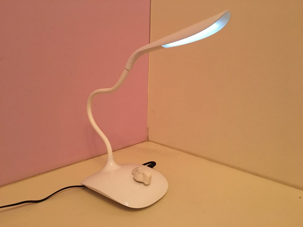
I found a nice white LED lamp with a long adjustable neck on eBay. It was driven from a USB PC connector via a small jack in the side of the lamp.
After a long wait for the slow boat the lamp arrived and worked great. It even had a battery inside so you could work away from the USB power point. Loved it. Until I opened it up.
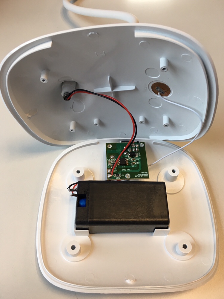
The battery charge controller was a diode from the USB 5v input to the battery. Nothing else. I hoped it had an internal charge control circuit in the lithium battery itself but couldn’t open it up to see. It’s an odd battery I’ve never seen one like it before. Usually they have some electronics on them even if it’s just to stop complete discharge from damaging the battery. It turned out this battery didn’t even have that. I flattened the battery on first use to the point where it no longer charges. I also noticed that the lamp didn’t have any CE or FCC marking. Heh-ho into the battery recycle bin ya go. The picture below shows the insides before modification.
The battery failure was a blessing really. My AC to 5VDC power converter wall wart which I had laying around gave out 5.2v nominal. So 5.2 – 0.7 = 4.5v, but lithiums shouldn’t be charged over 4.2v, not to mention the rate of charge needing to be controlled and the voltage will have a tolerance of +/-5%.
I based my design on the circuit in this link. It could probably be achieved using two comparators. One setup as a relaxation oscillator. But then it wouldn’t have the 555 timer street cred. Whatever works.
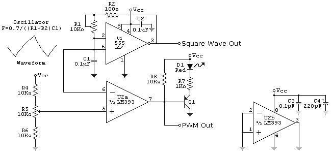
Essentially the circuit uses the 555 timer to generate the frequency. The output is a square wave. But we don’t use that output, we feed the capacitor C1 charge/discharge voltage from the input side (pin 6 on the 555) into a comparator which compares the voltage against a voltage reference generated from 2 resistors and a potentiometer. The resistors provide an offset so that you can achieve 0 to 100% duty cycle. In my case I increased the two resistor values (R4, R6) by 20% so that I could turn the lamp fully off in the minimum position and fully on in the maximum position. It’s a neat little circuit with many other applications.
A pot is used to change the 555 timer frequency. I chose a frequency of 1kHz to avoid flicker. The second pot is available on a knob outside the lamp which changes the duty cycle adjusting the LED brightness.
The output of the comparator is fed to a FET or transistor to turn the power on and off. I wired it to the gate of the FET in the lamps existing circuit after lifting a leg (the components not mine!). I also increased the value of the load resistor inline with the LEDs to 1.5kohm to reduce their brightness. This was probably a bit too much in hindsight but it worked well for the dim light it wanted at the time. Since then I’ve reduced the load resistor value to obtain more light. You have to be careful here not to overload the resistors power rating, I used 4 resistors to avoid this. It could also melt the plastic and wires if it gets really hot and become a fire hazard.
The only other issue I noted was that the comparator needed hysteresis to ensure a stable duty cycle. Luckily I had replaced the LM393 with the old Maxim MAX931 which I had laying around and it had a hysteresis feature built in. I believe I set it up for 20mV hysteresis in the end, though it could do with more. The only issue I can find is a flickering when the lamp is at about 1% brightness. Another 25 year old chip from my stores which I put to good use! I can’t understand why my wife thinks I keep lots of useless junk for years and years. It all finds a good use in the end?