Knowing the babies room temperature has become a bit of an obsession. When the temperature changes you need to make sure baby doesn’t wake up due to the cold or more serious still to make sure they don’t get too hot. SIDS is a worry in the back of every new parents mind. Not that it’s all based on air temperature. You can only properly test a babies temperature by checking the tummy or back with your hand and adjusting clothing accordingly. There are some rough guides on sites such as mothercare. Search for “how much bedding should I use for my baby”.
The Plan
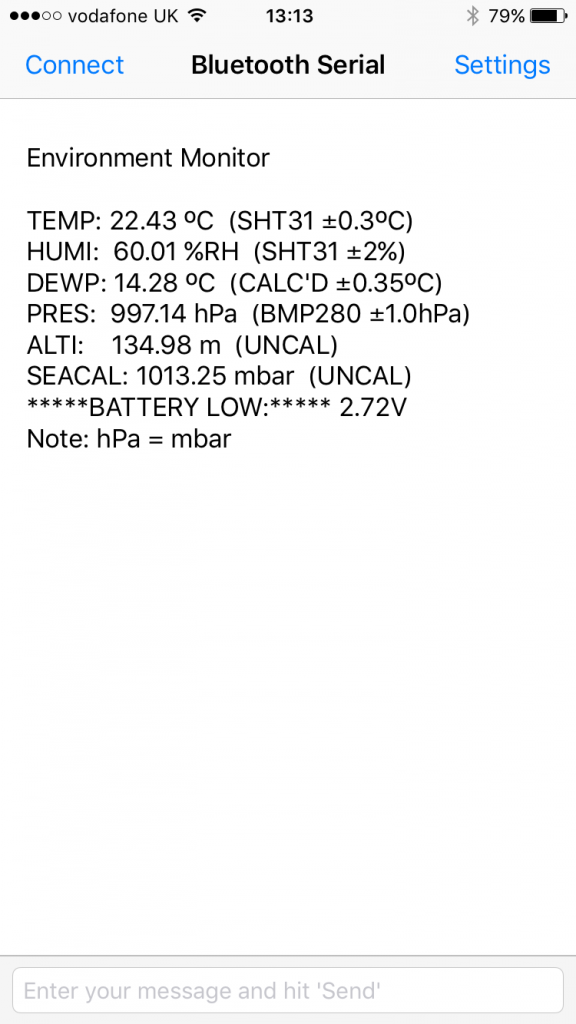
To help me check the room temperature and some other environmental stats I wanted to throw in there, I planned to put together a HM-10 Bluetooth LE module with temperature, humidity and barometric air pressure sensors plus battery power. This would allows me to check the details whilst in bed at 3am instead of getting up and poking my head around the door to look at the temperature monitor in babies room. We do have a baby video monitor by the way which tells the temperature. But it’s horribly inaccurate!
It also needs to be safe to leave in a room with a baby, meaning the battery enclosure at least needs securing so that the batteries cannot be swallowed.
I wanted to use BLE due to battery life but also because this thing was going to be transmitting near my baby and I don’t want musings in my head as to whether those RF signals are causing any harm to a developing brain. I figure BLE power levels are lower than Wi-Fi or GSM signals and not present for long in this application therefore it will be okay for occasional on demand sensor data requests.
How it worked out
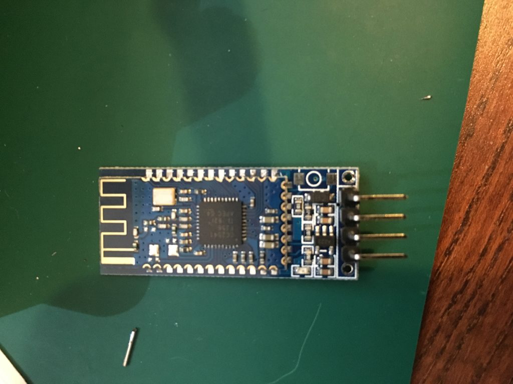
It worked in the end but it’s one of those projects that went a bit pear shaped early on. The HM-10 module is based on a Ti CC2541 chipset, the module is available on eBay. It is mainly used for connecting to Arduinos for example. I was going to program the TI chip itself with a CCDebugger programmer device also found cheaply on eBay and not use the Arduino at all. Unfortunately I realised after starting the project that the compiler for this TI chip costs thousands of dollars. You can get a 1 month trial by all accounts but who knows whether I’d get it completed in time as a part time hobby project.
So you adapt. After some looking around I settled on using an Arduino Pro Mini (3.3V 8MHz) board to serially drive the HM-10 and I2C sensors. Other than size the main difference between this 3.3v version and other Arduino 5v versions such as Arduino UNO is that it uses an 8MHz crystal instead of 16MHz and you use an external USB interface board. I say 3.3v but I’m actually using it at 3.0 v from batteries!
- HM-10 Bluetooth LE (smart)
- Sensirion SHT31
- BMP280
- Arduino Pro Mini 3.3V
- 2 x AAA or AA battery source
- Battery monitor via potential divider and Arduino internal ADC
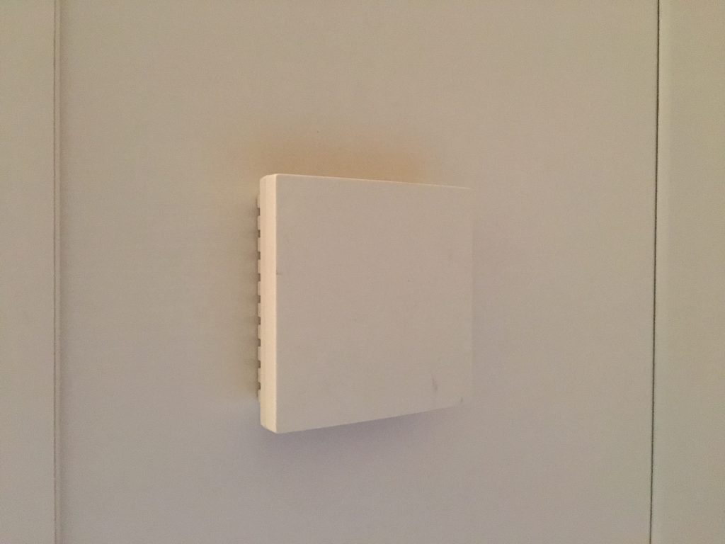
- A white wall mount sensor enclosure (from Ali-express)
The HM-10 module I purchased turned out to be a less impressive clone by manufacturer Bolutek. You can tell them apart by the crystals, the Bolutek boards only have one on-board crystal. It also had 4 pins present instead of 6 though the footprint was there for 6 pins. Software wise it’s serially driven AT command set was different and also required line feed and carriage return at the end of the AT commands unlike the original which didn’t need them. Ultimately I also found I couldn’t get the iBeacon mode working. The current draw was higher than expected in low power mode, the STATE pin wasn’t soldered to the daughter board, the regulator left 2v on the power line in power down mode and a few other little issues.
That would explain why it was cheaper! I didn’t want to wait another month for the slow boat to arrive with an original module so the project continued based on using the clone board.
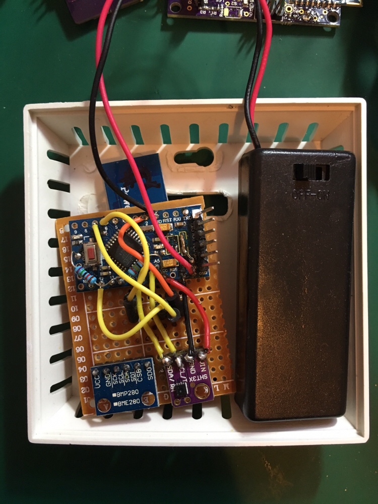
Connecting the Arduino board to the HM-10 was easy enough though I should have tried it out on breadboard first instead of hard wiring which would have saved time in the long run. As usual with serial the old “is TX inny or outy” reared its head but the HM-10 indicated direction on the board itself which is helpful. The power for the HM-10 is supposed to be more than 3.6v but I was using 3.0v from battery or 3.3v from the separate USB to serial adapter required for the pro mini due to lack of on board converter. It functioned anyway as it was so that’s how I initially used it until it was modified later to remove the regulator and other parts on its input feeding the power to the chips directly from the battery.
Buying cheap parts off eBay is nice but then you can have other issues to deal with. The nice cheap SHT31 and BMP280 were both 3.0v compatible which worked with the 3.3V Arduino and 3.0v batteries I wanted to use. So their lack of 5v level shifter wasn’t an issue, but these devices had a different I2C address than the drivers downloaded from Adafruit and elsewhere so the library needed modifying. An I2C scan was helpful here. After modification the results popped out nice and easy. I added dew point calculation for the heck of it with the help of a simplified formula found on Wikipedia.
Battery monitor
The battery is monitored via two high value 1% resistors connected at the mid point to the Arduino ADC input. The high value is to stop current drain through the resistors. Unfortunately this high value along with the 1% resistor tolerance introduces a slight measurement error of about 15mV as a result. That was fine for this application. The ADC reference was also set to 1.1v (INTERNAL). So the resistors to the ADC were scaled accordingly to make sure the input was always going to be below that voltage.
R1 = 240k 1%, 3.3v to ADC input
R2 = 75k 1%, ADC input to ground
Low power mode
The low power modes needed some hardware and software mods to make it work at the lowest power level possible. In a nutshell this involved:
- The BMP280 driver wasn’t in low power mode due to Adafruit library. Hack added to override the Adafruit library driver setting.
- The Arduino low power mode was simple to get going though exactly how it affects interrupts used elsewhere was never entirely clear. So it may be a source of instability given BLE serial comms is software serial and interrupt driven delay in ms is also used extensively in the software.
- HM-10 STATE pin is used to wake the Arduino from standby
- The HM-10 module has an auto low power mode turned on via AT command
- Further HM-10 power reduction was achieved by reducing the advertising interval, but take it too far and it didn’t always come out of standby.
- See hardware changes for physical board level improvements
- Ultimately a standby mode power consumption of 0.7mA was possible measured across a 1 ohm resistor in the power line. I was hoping for below 0.4mA to give good battery life. At some point I expect to switch from AAA to AA batteries which will double the lifetime.
Arduino software
The arduino software for this project can be found on GitHub. It’s no work of art, more an organically grown ugly fruit! Search for my username MVW123.
Smartphone app
After some time spent playing with ibeacon mode without success I switched back to using serial mode. There are several apps on the iPhone for the HM-10 Bluetooth serial comms, but I can only find one which works with this clone board in serial mode. Link below.
Using serial presented its own issues such as when to send data and how to detect a connection. This project uses the HM-10 clones STATE pin to indicate a serial connection. The STATE pin is checked and after outputting serial environmental data the HM-10 is turned off to reset the device cleanly.
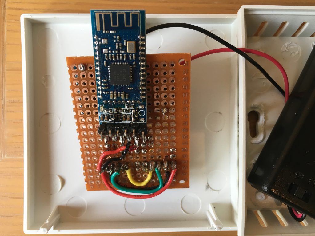
Due to my board having 4 instead of 6 pins connected I had to wire in the other 2 pins to get the STATE and power enable pins to work. By the way the HMsoft boards use different pins to the STATE and power enable pins.
Hardware changes
- Wired in the extra two HM-10 pins which were not connected on the pin header
- Soldered all pins on the HM-10 daughter board to the mother board
- Changed HM-10 regulator for a p-channel FET for lower quiescent current and inverted its control in software
- Removed the Arduino power LED
- Removed the Arduino regulator and rewired the diode and changed the re-settable fuse for a 100mA version
- Added battery sense resistors
- Fixed the faulty battery holder…
In hindsight the 100mA fuse had 8 ohm resistance so it’s not the best choice due to volt drops and ripple caused by current variations, though it is safer in a fault condition.
OLED display
Ultimately I removed the SPI OLED 0.96″ display from the project. But it was good to see the sensor data on the screen whilst the project was under development. Adding the display caused unexpected problems. The Adafruit driver uses a large chunk of memory and combined with other drivers there was no room left in the micro causing gremlins to be unleashed. I also wonder about interrupt clashes going on in the background.
After trying a couple of other drivers I found a text only display driver which worked well enough except for some shenanigans at the bottom of the screen which was never bottomed out and the screen flashed which could be how i’m using it.
Final thoughts
The project worked though not as I initially wanted it to and didn’t achieve its low power battery life aims. Range was fine in my small house though larger homes may not be so lucky. The HM-10 is BLE 4.0. New BLE 5.0 devices such as the nrf52 series are starting to come out which would be lower power and better performance. The Arduino environment supports directly programming the Nordic nrf5 series so that would seem like a better option. Also support seems much better on the Nordic website than for the HM-10 module. So that would be my preferred direction if I had it all to do again.
I could of course have turned off the HM-10 BLE module after use, this would require quite a few changes to my software but would hugely extend the battery lifetime.
One alternative to all of this is using a cheap Wi-Fi module. Which is woken every 20 minutes or so to log the temperature to the cloud. There are nano power timer ICs to allow this to happen and I notice someone has this very project available on tindie already. Alternatively a Bluetooth to Wi-Fi bridge would also work. This would allow a much nicer app interface than the serial port I’m using. I have it in mind to do this on a future project. But as mentioned earlier I’m not certain I want Wi-Fi transmitters next to the baby’s cot. Yes I use a smart phone in the same room as the baby, though I try not to do that when it’s next to his head. Is there an issue there? I’ve no idea. After a look around I can’t see convincing proof of any issues but why take the risk. You can’t change what you’ve already done.
For the future, It would be useful to be able to log temperature over a few days and plot it but I don’t currently have that facility. [Update] See my newer post for the Bluetooth and Wi-Fi hub design.