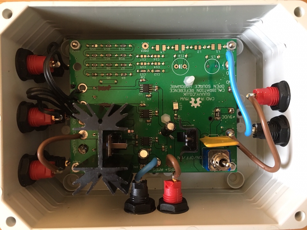
I got a little carried away with this one! I have an old multi-meter whose calibration was unknown. Surely an accurate voltage reference would help with that. After spending somewhere around £80.00 designing and building a calibrator for my cheapo old multi-meter i feel I’ve given this project more than it needed:-)
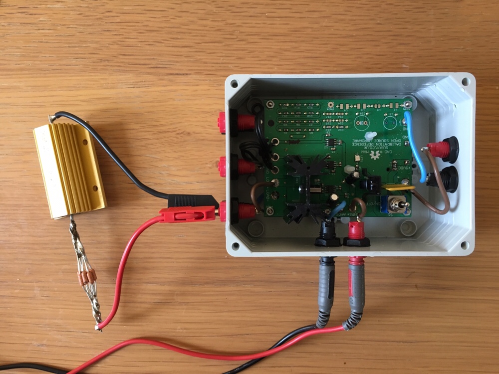
There are a few things I’d do differently. The current reference isn’t very accurate it needs external sense wires to the external reference resistor. The huge 1 ohm external reference resistor is 5% tolerance so it needs its resistance tweaking. In fact I’d replace the circuit with a tight tolerance SMD current reference resistor and then use an external power supply whose voltage drop was measured against the voltage reference. This also gets rid of the large heat sink and associated components.
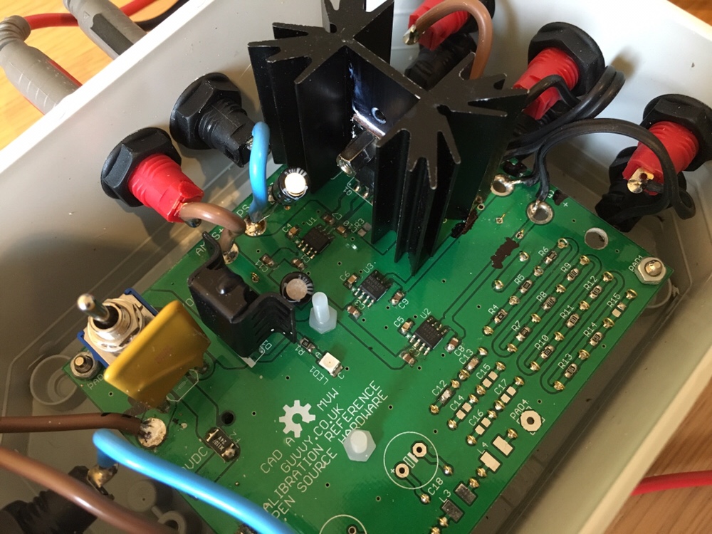
The voltage reference would be better being a type which has an external cermet potentiometer to tweak its reference value against a more accurate calibration source. TI do a range of parts which would be suitable.
The gold test points were a nightmare to solder given there were so many – about 110? Larger test point holes for probing would have been good enough.
The RLC reference components were okay though tight tolerance inductors are hard to come by. Overall I needed less of them and needed their values noting on the PCB so they were not forgotten.